What is Camera Pan and Tilt
What is Camera Pan/Tilt?
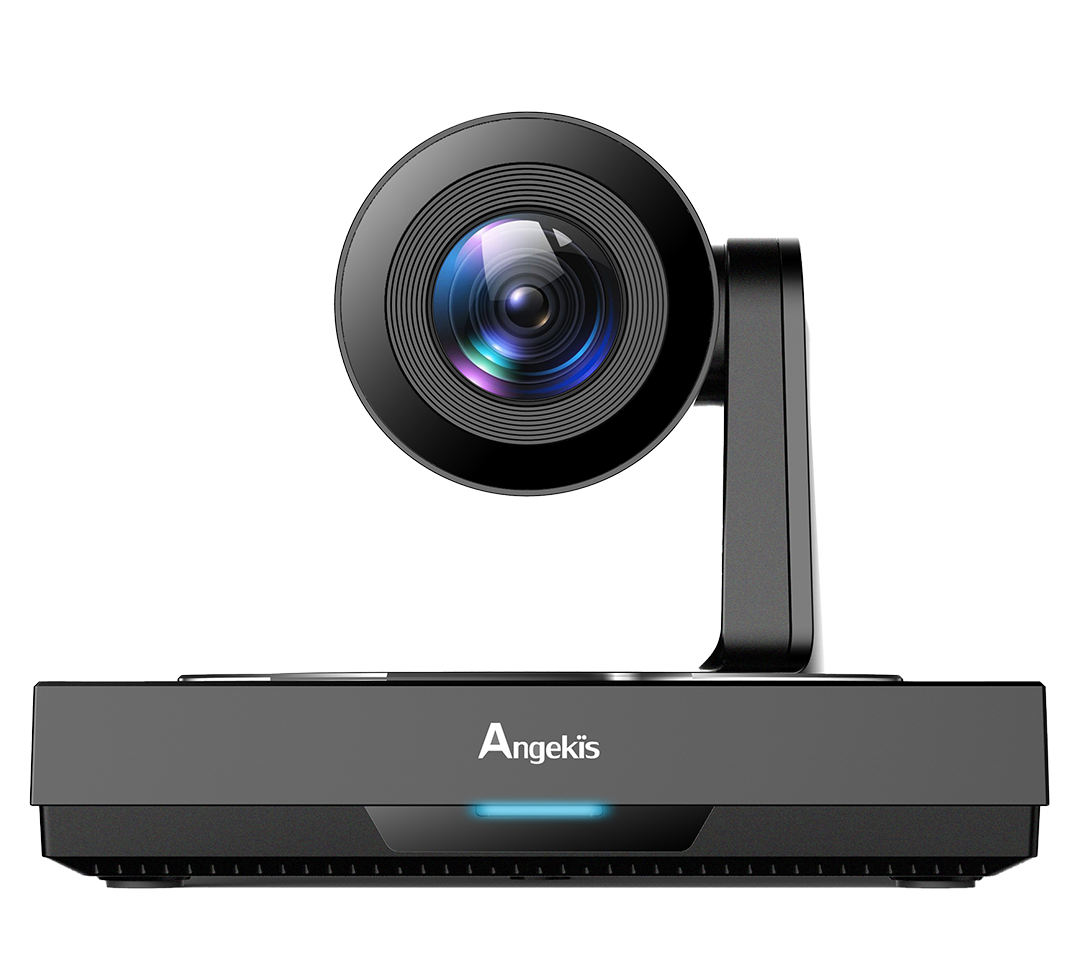
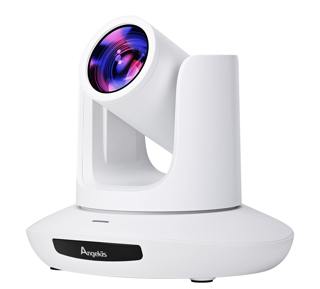
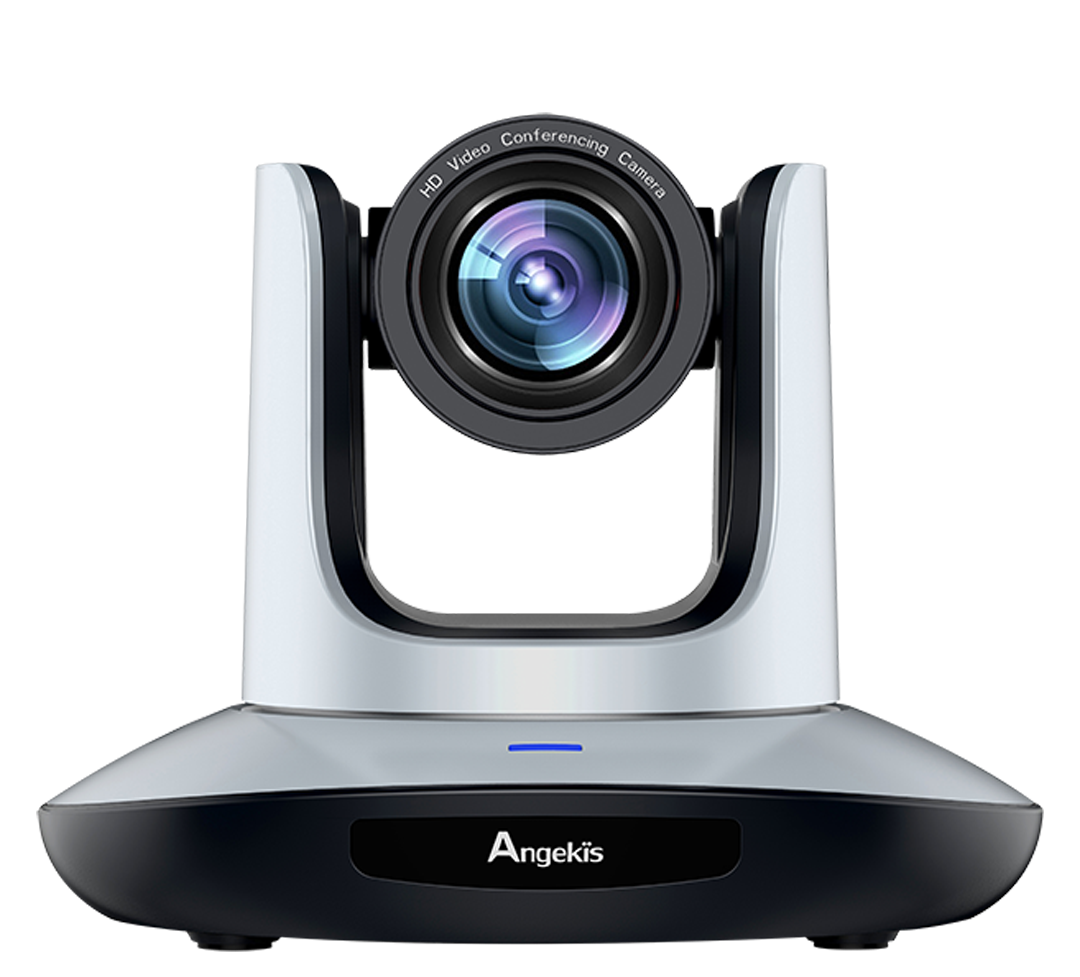
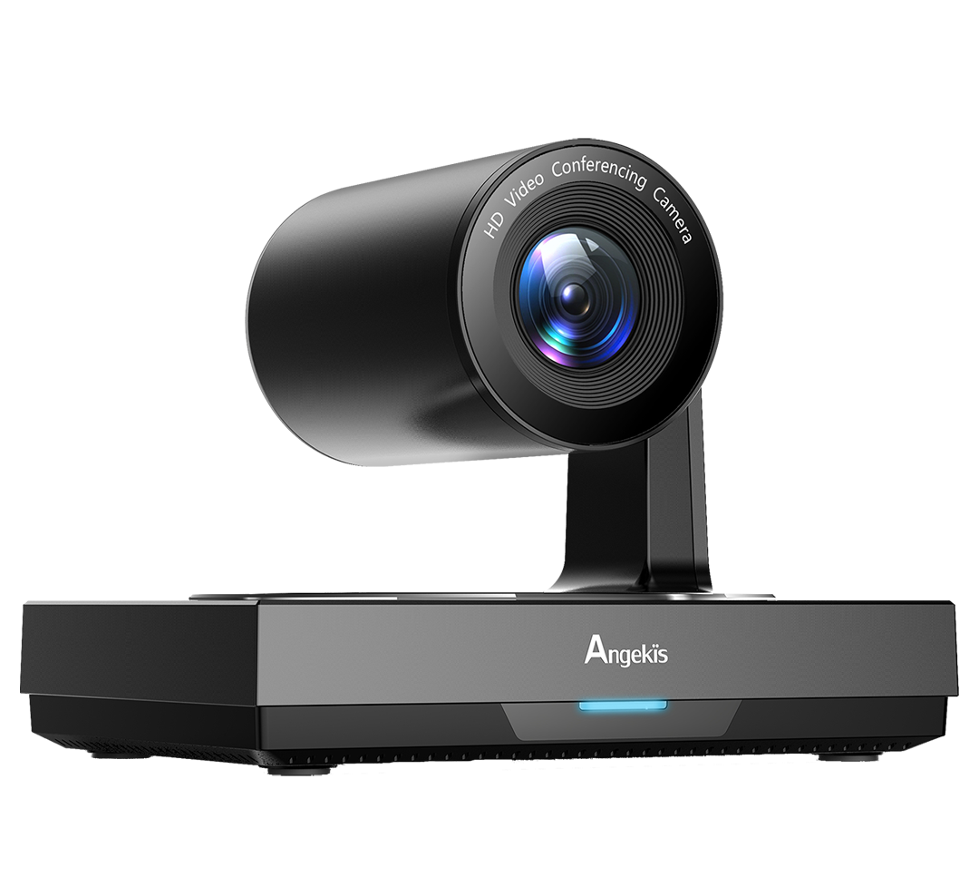
Camera pan/tilt is a built-in accessory function that allows the camera supports to change the angle of the camera horizontally, as well as vertically. The actual mechanism that allow this movement is the Gimbal.
While the Pan/Tilt mechanisms in your Angekis PTZ Camera are sturdy, reliable, and more than capable for their use-case, the technical possibilities for this technology are endless.
1. Technical Classifications of Gimbal Parts and Functions
The gimbal (pivoted support) is divided into horizontal gimbal and omnidirectional (omnidirectional) gimbal according to the movement function.
According to the working voltage, there are both AC fixed-speed gimbals and DC high-speed gimbals.
According to the carrying weight, they are divided into light load head, medium load head and heavy load head.
According to the load installation method, they are divided into top-mounted gimbals and side-mounted gimbals.
According to the use environment, they are divided into general type and special type. Universal type refers to use in non-flammable, non-corrosive gas or dust environments.
In the atmospheric environment, they can be divided into use type and outdoor type. The most typical special application is the explosion-proof pan/tilt.
1.1 Internal structure of the unit
There are two motors inside the omni-directional gimbal, which are responsible for the rotation of the gimbal up and down and left and right. The difference of the working voltage also determines the overall working voltage of the gimbal. Generally, there are AC 24V, AC 220V and DC 24V. When receiving the upper and lower action voltages, the vertical motor rotates, and the vertical transmission wheel is driven to rotate through the reduction box; when receiving the left and right action voltages, the horizontal motor rotates and drives the horizontal gear plate at the bottom of the gimbal to rotate through the reduction box. .
It should be noted that the gimbal has horizontal and vertical limit bolts, and the gimbal has two micro switches to realize the limit function. When the rotation angle reaches the preset limit bolt, the micro switch will cut off the power supply, and the pan/tilt will stop rotating. The limit device can be located outside the gimbal, and the adjustment process is simple, or it can be located inside the gimbal and adjusted through the adjustment mechanism of the peripheral device, and the adjustment process is relatively complicated. However, the sealing performance of the gimbal with the external limit device is not as good as that of the gimbal with the built-in limit device.
The outdoor gimbal is basically the same as the indoor gimbal, but the load capacity of the gimbal must be increased due to the large weight of the outdoor protective cover. At the same time, the temperature of the outdoor environment varies greatly, and it is easily eroded by rain or moisture. Therefore, outdoor heads are generally designed to be sealed and rain-proof. In addition, the outdoor gimbal also has high torque and choke protection circuit to prevent the gimbal from being forced to start and burn the motor when it freezes. Under the harsh conditions of low temperature, a temperature-controlled heater can also be installed inside the gimbal.
2 Performance Indicators of the Gimbal
2.1 Rotation speed
The rotation speed of the gimbal is an important indicator to measure the grade of the gimbal. The horizontal and vertical directions of the gimbal are driven by two different motors, so the rotation speed of the gimbal is also divided into horizontal speed and vertical speed. Due to the load, the torque of the vertical motor is greater than the torque in the horizontal direction when starting and running, and the horizontal speed is higher than the vertical speed when adding actual monitoring horizontal speed.
The AC gimbal uses an AC motor with a fixed rotation speed. Generally, the horizontal rotation speed is 4°/sec to 6°/sec, and the vertical rotation speed is 3°/sec to 6°/sec. Some manufacturers also produce AC-type high-speed gimbal, which can reach horizontal 15°/sec and vertical 9°/sec, but the high-speed load capacity of the same series of gimbal will be reduced accordingly.
Most of the DC type gimbals use a DC stepping motor, which has the advantages of high speed and variable speed, which is very suitable for occasions that need to quickly capture the target. The maximum horizontal rotation speed can reach 40-50°/sec, and the vertical speed can reach 10-24°/sec. In addition, the DC PTZ has a variable speed function, and the voltage provided is a variable voltage between DC 0 and 36V. The effect of variable speed is determined by the performance of the control system and the decoder, so that the gimbal motor can rotate at the corresponding speed according to the input voltage. There are two common speed change control methods, one is full speed control, which determines the input voltage to the gimbal by detecting the displacement of the operator on the keyboard joystick. The other is the step-by-step progressive control, which is to set several gears within the variable speed range of the gimbal, and each gear corresponds to different voltages (rotational speeds).
2.2 Rotation Angle of the Gimbal
The rotation angle of the gimbal, especially the vertical rotation angle, has a lot to do with the installation method of the load (protective cover/camera/lens assembly). The horizontal rotation angle of the gimbal can generally reach 355°, because the limit bolt will occupy a certain angle, but there will be a little monitoring dead angle. The current PTZ has improved the limit device so that it can reach 360° or even 365° (with 5° coverage angle) to eliminate the monitoring dead angle. The user can set the limit according to the actual situation on site. For example, the wall-mounted type installed on the wall, even if the pan/tilt has a 360° rotation angle, you only need to monitor the 180° angle of the front of the pan/tilt, even if the pan/tilt is rotated to the rear direction. Only the installation surface (wall) can be seen at 180°, which has no actual monitoring significance. Therefore, the wall-mounted type only needs to monitor the horizontal 180° range, and the corner-mounted type only needs to monitor 270° range. In this way, the gimbal is prevented from being rotated too much to a position that does not require monitoring, and the use efficiency of the gimbal is also provided.
The vertical rotation angle of the top-mounted gimbal is generally +30° to -90°, and the vertical rotation angle of the side mount can reach ±180°, but in normal use, the vertical rotation angle is +20° to -90°.
2.3 The Load Capacity of the Gimbal
The maximum load of the gimbal refers to the maximum load capacity that the gimbal can bear in the vertical direction. The distance between the center of gravity of the camera (including the protective cover) and the working surface of the gimbal is 50mm. The center of gravity must pass through the center of gimbal rotation and be perpendicular to the working surface of the gimbal. This center is the maximum load point of the gimbal and the bearing capacity of the gimbal. This point is used as the benchmark for design calculations. If the load position is improperly installed, the center of gravity deviates from the center of rotation, and the load moment is increased, and the actual load capacity will be less than the design value of the maximum load capacity. Therefore, the greater the vertical rotation angle of the gimbal, the greater the deviation of the center of gravity, and the smaller the corresponding bearing weight.
The load capacity of the gimbal is the key to the selection of the gimbal. If the load capacity of the gimbal is less than the actual load, not only the operation function will be reduced, but the motor and gear of the gimbal will also be damaged due to long-term overloading. The actual load capacity of the gimbal can vary from 3kg to 50kg. For the same series of gimbal products, the bearing capacity of the side mount is greater than that of the top mount, and the bearing capacity of the high-speed type is smaller than that of the ordinary one.
2.4 Using Environmental Indicators
The requirements of the gimbal for indoor use are not high, and the indicators of the use environment of the gimbal are mainly for the gimbal used outdoors. These include the use of ambient temperature limits, humidity limits, and IP ratings for dust and water resistance. Generally, the temperature range of the gimbal used in the outdoor environment is -20°C to +60°C. If it is used in a lower temperature environment, a temperature-controlled heater can be installed inside the gimbal to make the temperature lower limit reach -40°C or lower. The humidity index is generally 95% non-condensing. The IP rating for dust and water resistance should be above IP66. The level of IP protection reflects the degree of sealing of the equipment, mainly referring to the intrusion of dust and liquids. The first value after IP represents the degree of sealing protection against solids, the second digit represents the degree of protection against liquids, and the third digit represents mechanical shock resistance. In addition, in actual use, suitable materials and protective layers should be selected and used according to the environment. For example, iron shells are not suitable for use in humid and corrosive environments.
IP rating meaning (IPxx)
IP first second second
0 No protection No protection
1 Solid matter up to 50mm, such as accidental contact with hands, vertical drop, or contact with water, such as condensation.
2 Solid substance answer 12mm, such as finger Direct spray of water, inclination not more than 15°.
3 The solid material exceeds 2.5mm, such as tools, wires, water spray, and the inclination does not exceed 60°.
4 Solid objects over 1mm, such as tools and thin wires.
Water sprays from all directions, allowing limited intrusion.
5 Dust tight - limited ingress (guaranteed no damage to equipment).
Water is injected at low pressure from all directions, allowing limited intrusion.
6 Safe and dustproof. Water is injected under high pressure from all directions, such as cabins, allowing limited intrusion
7 Immerse underwater for 15cm to 1m
8 Prolonged immersion in water
2.5 Hysteresis
Backlash is also known as gear backlash (Gear Backlash), which is an important indicator to examine the rotation accuracy of the gimbal.
2.6 Reliability
The reliability of the gimbal is generally measured by indicators such as mean time between failures (MTBF), mean time to repair (MTTR), mean time between failures (MTTF), and limit times of active switches.
3 PTZ for special purpose
The application range of the gimbal is very wide, and various special industries also have certain requirements for gimbal products. Due to the special use environment, gimbal products are required to have special protection performance to meet the on-site environment. The common ones are underwater type, high temperature type, low temperature type type, anti-corrosion type and explosion-proof type. Special gimbals have strict requirements on the materials, protection levels, and protection methods used, and must comply with the corresponding industry-specific standards. Among them, the explosion-proof PTZ is the most prominent.

