
Blade VS+
Saber 4K+
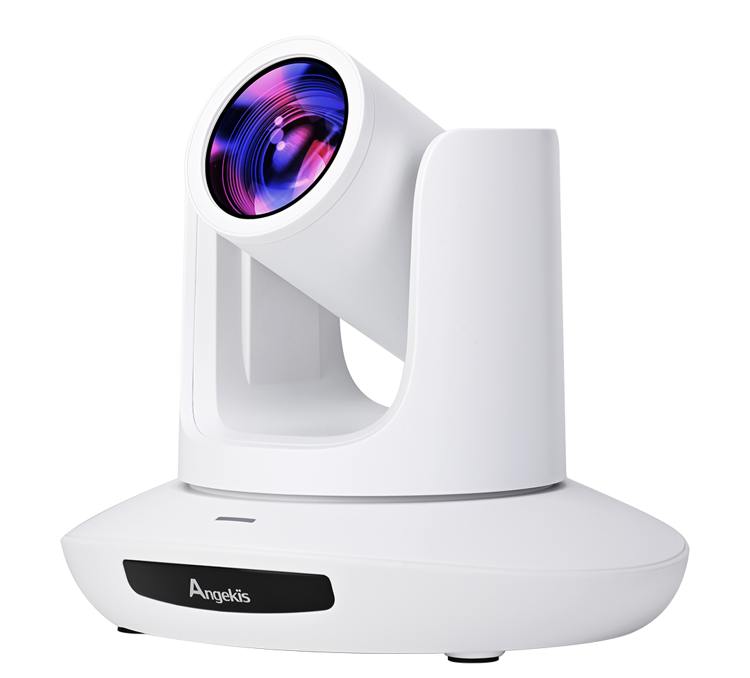
Saber X
Saber U20
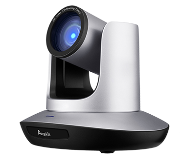
Saber Plus
Saber IP20X
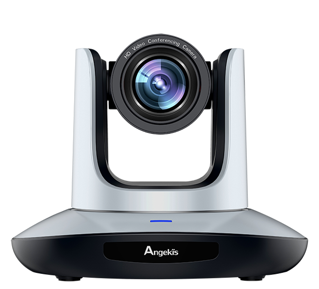
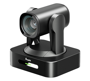
Saber Light

Saber 4K+ NDI®

Saber IP20X NDI®
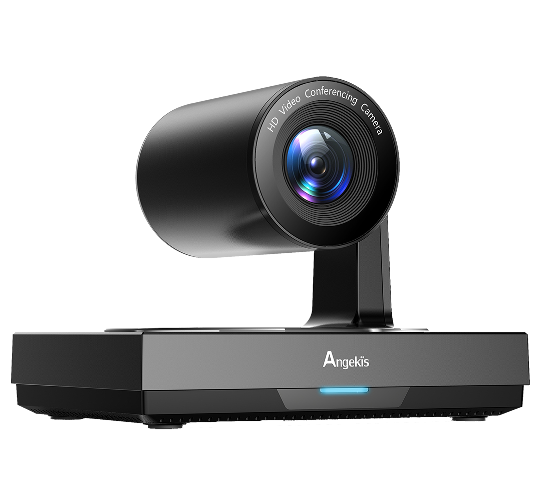
Blade 4K
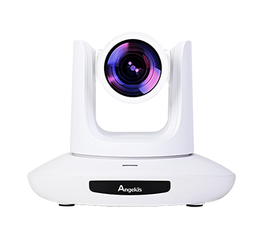
Saber 4K

Saber AT

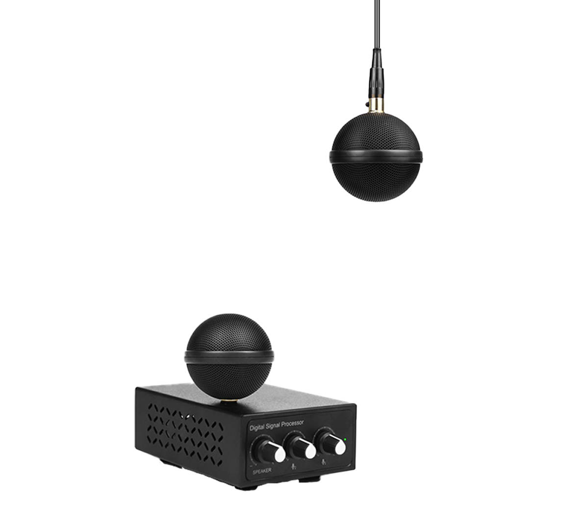
Cleartalk Wired ASP-05
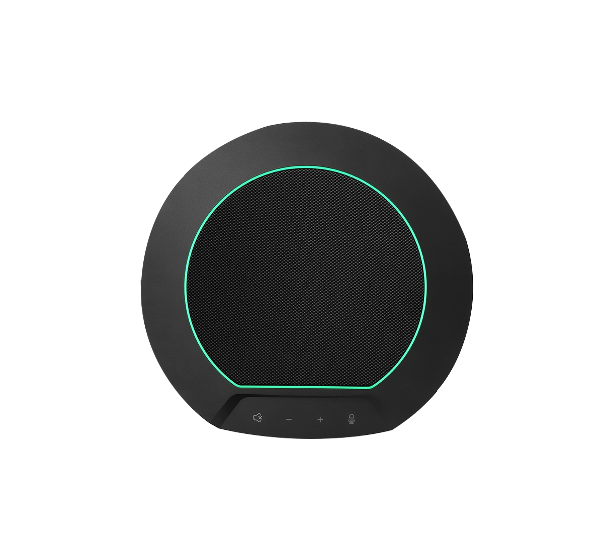
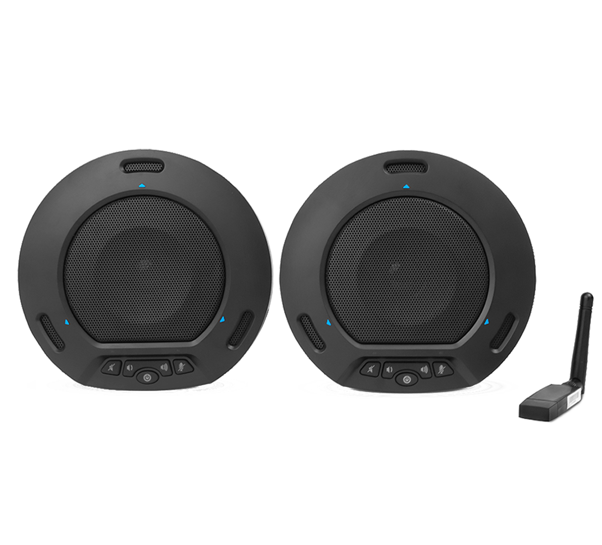
Cleartalk HD ASP-10

Cleartalk Wireless ASP-04
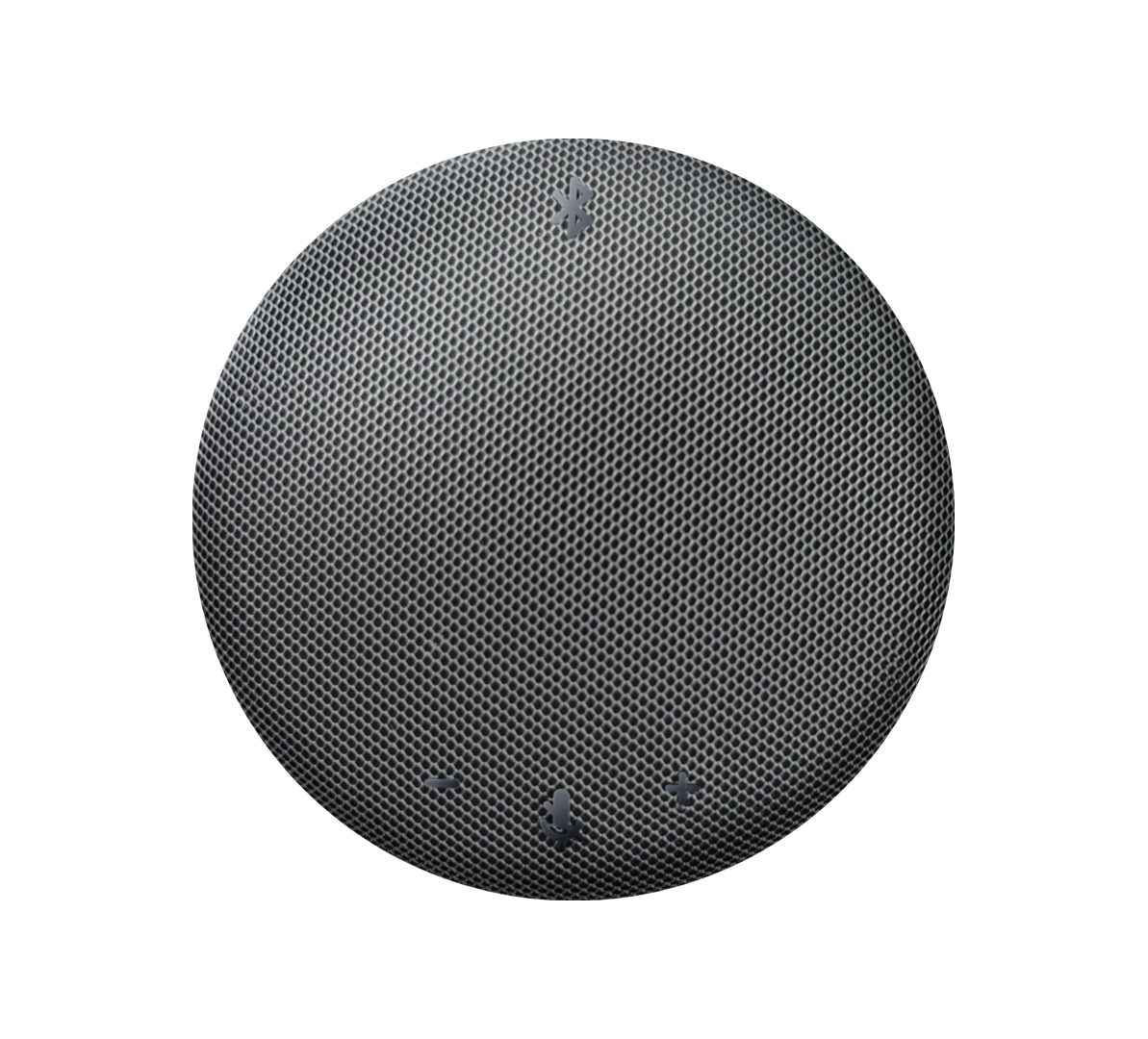
Cleartalk Anchor ASP-06
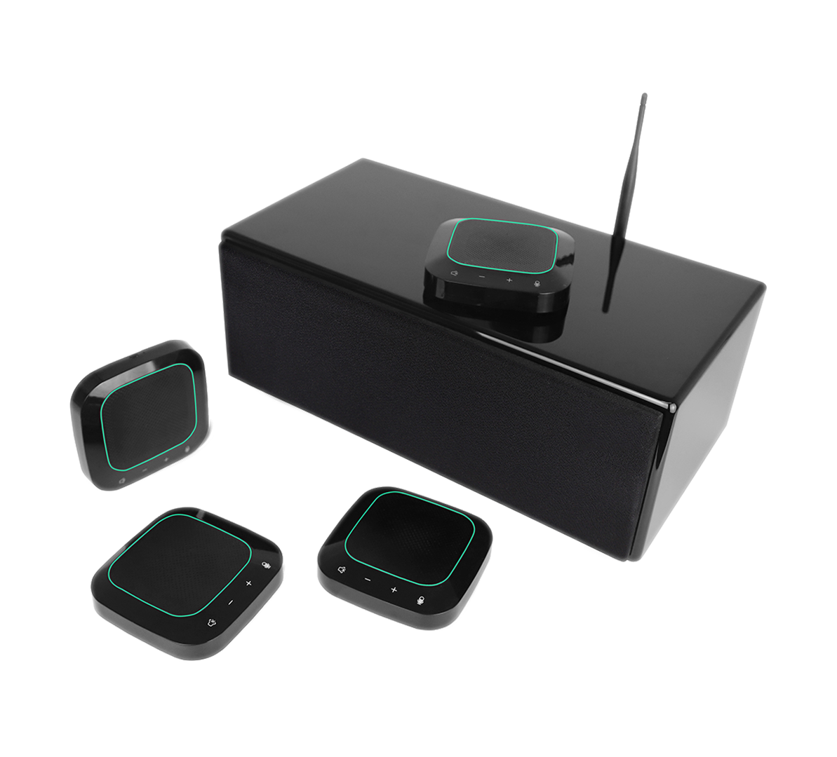
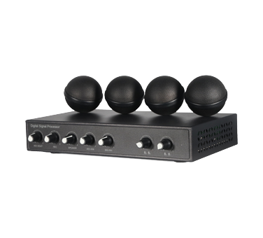
Cleartalk DC 4 Units ASP-04D-4S

Ceiling Mic Pro ASP-C-01
Ceiling Mic Pro ASP-C-02
Ceiling Mic QS ASP-C-04
Cleartalk DC 2 units ASP-04D-2
Cleartalk HD DC ASP-10D-2
Mission Control Keyboard
Wall Bracket (White)
Wall Bracket (Black)
USB3.0 Extend Cable 10-30M
USB3.0 A male to B male Active Optical Cable
USB3.1 Type A-C Active Optical Cable
HDMI 2.0 Cable
Ceiling Mount (White)
Ceiling Mount (Black)
USB2.0 Extender
One Touch Wall Bracket (Black)
IP Controller
Remote Control for Saber and Blade
Cord Cover Wall Bracket (Black)
Remote Control for One Touch
Cord Cover Wall Bracket (White)
RS232 Cable
RS232 Joystick
Power Adapter

Blogs
The Working Principles of Your Angekis PTZ Digital USB Camera
The Working Principles of Your Angekis PTZ Digital USB Camera
This article provides a brief introduction to the working principle of your Angekis PTZ Digital USB camera.
1. The Basic Working Principles
As light enters the camera, an optical image is generated by the lens (the optical glass hemisphere on the front of the camera) and projected onto the surface of the CMOS image sensor. This sensor converts this information into an electrical signal, which is then converted into a digital signal through A/D (analog-to-digital conversion) and then sent to the digital signal processing chip (DSP) for further processing. At this point, the signal can be output through one of the ports on the back of the camera (HDMI, SDI, USB) or converted into another signal type (such as NDI, SRT, RTMP) and output through the LAN port.
2. Data Format.
The signal output from the DSP sensor array is only monochromatic at each pixel. This data, which is directly output by the sensor and has only monochromatic information for each pixel, is called Raw RGB data. The sensor array will also collect information on the color of the light hitting each pixel sensor. The purpose of the DSP is to take the Raw RGB data and turn it into real RGB or YUV format data through calculation and post-processing to include color. In short, the DSP's main job is to convert the Raw RGB format to RGB or YUV format.
ISP (Image Signal Processing) or DSP (Digital Signal Processing) is a device that processes images. These processed imaging data can be used directly by AP processors or baseband chips, and whether the common image format data is reprocessed, displayed or saved depends on the application requirements of each platform.
RGB Data: Theoretically, any color can be created with three basic colors: red (R), green (G), and blue (B), and RGB are known as the three primary colors. In data transmission, one byte is 8 bits, and RGB565: 16 bits in total, accounting for two bytes. Therefore, the total number of colors that can be expressed is 2^16 = 65536, of which red R and blue B can be expressed as 32 different values, and green G can be expressed as 64 different values; RGB24: 24 bits in total, accounting for three bytes. RGB has 8 bits for each of the three colors, so the total number of colors that can be expressed is 2^24 = 16.77 million colors, and each color can be expressed as 256 different values; ARGB32: 32 bits in total, accounting for four bytes. The three RGB colors each take up 8 bits, and the remaining 8 bits represent the Alpha channel value, so the total number of colors that can be represented is 2^24 = 16.77 million colors, and each color can be represented as 256 different values. But because the alpha value is added, each color can also be displayed as 256 different transparency values.
The principle of YUV is to separate the luminance (brightness) from the chromaticity (color), and research has proven that the human eye is more sensitive to luminance than chromaticity. The three letters of YUV, in which "Y" means Luminance and "U" and "V" means Chrominance, describe the image color and saturation, and are used to specify the color of a pixel. The importance of using the YUV color space is that its luminance signal Y and chrominance signals U and V are separated.
The formula for converting YUV data and standard RGB data to each other:
Y = 0.299R + 0.587G + 0.114B
U = 0.147R - 0.289G + 0.436B
V = 0.615R - 0.515G - 0.100B
R = Y + 1.14V
G = Y - 0.39U - 0.58V
B = Y + 2.03U